
Most injection molds are not worn out. They are ruined between runs — a month on a rack with water still in the channels, a fingerprint on a polished cavity, a parting line pressed shut one time too many. The wear that everyone plans for is slow and predictable. The damage that actually ends a tool’s life usually happens while nobody is producing anything.
What actually wears out, and what does not
A mold is not a uniform block that slowly erodes. Damage concentrates in a handful of places, and each one has a signature that shows up long before it becomes a scrap bin full of parts. Knowing the signature is the whole skill.
| Component | How it fails | First visible sign | What it does if ignored |
|---|---|---|---|
| Leader pins and bushings | Clearance opens up as the bronze or steel wears | Feeler gauge of 0.02–0.03 mm slips between the parting faces at one corner but not the others | The halves close slightly offset, so flash appears on one side only and grows. Adjusting lock force makes it worse |
| Parting line (shut-off face) | Repeated closing peens the steel over, so the face is no longer flat | A bright, polished band or a smear of white powder along the parting line | Flash everywhere along that band, then more flash as the peened metal is pressed further. It self-accelerates |
| Gate and sprue bush | Abrasive resin washes the hole larger | Gate vestige getting taller, or packing no longer reproducible from shot to shot | Cosmetic rejects at the gate, and a cushion that drifts. Eventually the gate cannot be re-cut |
| Ejector pins and their bores | Pins bend; bores wear oval | Ejector marks standing proud of the surface, or a thin film of flash creeping out of a pin hole | Parts stick, pin marks become visible, and resin migrates into the ejector plate |
| Slides and lifters | Guide wear lets the slide sit lower each cycle | Flash at the slide shut-off, or a polished drag mark on the core face | Undercuts go out of tolerance, then the slide galls and seizes. A seized slide stops the tool |
| Vents | Not wear — blockage. Oil, release agent and washing fluid bake into the 0.02 mm slot | Burns or a dark sheen at the end of fill, short shots that move around, a hiss that has gone quiet | Burns become a permanent cosmetic defect, and filling is only achieved by raising pressure, which raises flash elsewhere |
| Water circuit | Scale deposits, and residue left to sit when the tool is idle | Return temperature drifting up, flow meter reading dropping, rust bloom in the channels | Cooling degrades on one side of the tool only. Dimensions drift and no amount of machine adjustment brings them back |
Two entries in that table are worth dwelling on, because they are the ones people misdiagnose.
The first is the parting line. When a tool closes, the shut-off faces meet under full clamp force. The steel does not simply touch — the edge gets peened over, a few microns per hundred thousand cycles, like a chisel that has been struck too often. The face is no longer flat, so flash starts, so the operator raises clamp force to stop the flash, which accelerates the peening. That loop is why a mold that ran perfectly for a year suddenly produces flash and never stops. The correct response is to stop, measure, and re-spot. The wrong response, which is the usual one, is more tonnage.
The second is the water circuit. Everything else in the table announces itself on the part. Cooling does not. A circuit that has lost half its flow still produces parts that look fine — until the dimensions start drifting on one side of the tool, and the setter spends a shift adjusting holding pressure to chase a cooling problem. By the time anyone checks the return temperature, the scale has been building for months. In practice, when a dimension moves and the machine is healthy, check the water before touching a single process parameter.
What rarely wears out is worth saying too. The mold base plates themselves almost never cause a dimensional problem unless they rust. The cavity steel wears very slowly in normal service — which is why the steel grade matters more for corrosion and polishability than for abrasion in most applications. Most "the mold is worn out" verdicts are really about fits, shut-offs and water, not about the cavity block being consumed.
The four maintenance cadences
Maintenance schedules fail when they are written as a calendar. A tool running three shifts needs attention on a different rhythm from one that runs two days a month. The useful structure is four levels, each with a different owner, because the value of the schedule is not the frequency — it is the name next to it.
| Cadence | Who signs it | What is actually done | Time |
|---|---|---|---|
| Every shift | Machine operator | Look at the parting line, the ejector marks and the water readings. Listen to the slide. Check for leaks under the platen | 5 minutes |
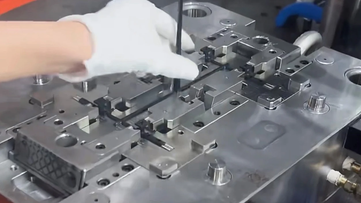
| Weekly | Setter or technician | Wipe and inspect the shut-off faces, clear the vents with a brass shim, grease leader pins and slide ways, tighten clamps, check hose barbs | 30 minutes |
| Every 50,000–100,000 shots | Toolmaker | Measure leader pin clearance, inspect shut-off faces for peening, polish the cavities, flush the water circuit, check ejector bores | Half a day |
| Annual or 500,000 shots | Toolroom, tool off the machine | Strip down, measure all working fits, replace wear items, re-spot the parting faces, full descale, re-protect and re-store | 2–5 days |
Three things make this work in practice.
Low-volume tools need a calendar anyway. A mold that runs 20,000 shots a year will never reach the shot-based milestones, and yet it is the one most likely to rust, because it spends eleven months idle. For those tools, replace the shot count with months: inspect and re-grease every six months whether or not it ran.
The weekly task is the one that gets skipped. It has no visible output, it competes with a changeover, and it is easy to defer. It is also the cheapest hour in the whole schedule, because clearing a vent takes a brass shim and ten minutes, while a blocked vent bakes carbon into the steel and needs polishing to remove.
Vents are cleaned, not inspected. A vent is a slot around 0.02 mm deep. You cannot see whether it is open by looking. Pass a brass shim through it, or measure the fill pattern — if the end of fill has moved or darkened, the vent is closed.
The five-minute check between shifts
This is the only maintenance most tools ever receive, so it has to be short enough that an operator will actually do it at the end of a shift. Six items, no tools, no disassembly.
| Check | What good looks like | What to do when it is not |
|---|---|---|
| Parting line | One even hairline. No white powder, no polished band | Stop and flag it. A white band means peening has started and every further cycle makes it deeper |
| Ejector marks | Flush with the surface, or a controlled shallow dimple if the drawing allows it | Pull the pins and check for bend. A bent pin will oval its bore within a shift |
| Water in and out | Return 3–5 °C warmer than supply, flow at the set value | A widening gap means the circuit is scaling. Do not raise the chiller setpoint to compensate |
| Tool surface | Dry, no water marks, no rust bloom at the shut-offs | Dry it and find the leak. Water sitting on steel overnight is how cavities get pitted |
| Ejector plate | Fully home, no knock or rattle on the return | A plate that does not return will be hit by the core on the next close |
| Slides and lifters | Free movement, no squeal, no bright drag marks | Lubricate and re-check the same shift. A dry slide galls in hours |
The economics here are easy to underestimate. Six checks take five minutes, so a three-shift operation spends under half an hour a day on them. A peening band that goes unnoticed for a week typically means the tool comes off the machine, gets stripped, re-spotted and re-trialed — two to five working days, plus a production gap. One is a habit; the other is an event.
Give the operator a way to record a "no". A checklist that only records compliance is worse than none, because the one time something is wrong, nobody writes it down. A photo on a phone sent to the toolroom group is enough, and it costs nothing.
Water: the failure nobody notices until it is expensive
Cooling removes most of the heat the machine puts into the part, and in most tools it is the largest single block of the molding cycle. It does this through channels that are 8 to 12 mm across. That is a small hole with a lot of responsibility, and it is the part of a mold that degrades most invisibly.
Scale is a thermal insulator. Above roughly 40 °C, dissolved calcium and magnesium come out of hard water and plate onto the channel wall. A layer of a fraction of a millimetre measurably reduces heat transfer, and because the deposit grows from the wall inward, the effective channel gets smaller at the same time — so both the flow and the heat transfer fall together. Nothing about the part announces this on day one.
The idle period is the dangerous one
What makes it worse is the idle period. Water left sitting in a circuit for a week, with dissolved oxygen and a bit of residual heat, starts pitting the steel from inside. The pits then hold water, the next idle period pits deeper, and eventually a channel that used to flow freely is a rough, restricted tube that no amount of flushing will restore. Blowing the circuits dry at the end of a run is the single cheapest thing anyone can do to a mold, and it is the step most often skipped when a job ends in a hurry.
There is also a freeze risk that catches people in unheated buildings: water left in a manifold over a cold weekend cracks the plate. Manifolds and hot runner plates are the most expensive single component to replace, and they fail from something that a two-minute blow-off prevents.
Water quality matters more than most shops admit. Open cooling towers grow algae and carry suspended solids that settle in slow sections. Groundwater is often hard. A closed loop filled with softened or deionised water, filtered and changed on a schedule, is not a luxury on a tool expected to run for a decade — it is the difference between a mold that lasts and one that drifts out of tolerance in year three.
Reading a water circuit from three numbers
You do not need to disassemble anything to know the state of a cooling circuit. Three readings, taken at the same time each week, tell you almost everything.
| Reading | Healthy | What an abnormal value means | Action |
|---|---|---|---|
| Return minus supply temperature | 3–5 °C | Above 8 °C: flow is too low, or the circuit is scaled. Below 2 °C: flow is excessive, or the sensor is badly placed | Check flow first, then pressure drop. Descaling is the last step, not the first |
| Flow, litres per minute | At the value the mold design calls for | A 20 % drop from commissioning is significant even if parts still look fine | Compare each circuit separately. One low circuit is a blockage, all low is a pump or chiller problem |
| Pressure drop across the tool | Stable over months | Rising drop with falling flow is scale. Rising drop with steady flow is a partly closed valve or a kinked hose | Clean, do not simply raise pump pressure — that can burst an old hose |
| Spread between circuits on a multi-cavity tool | Within 2 °C | One circuit running hotter is the most common cause of a single cavity producing out-of-tolerance parts | Balance the manifold, then inspect that circuit. Do not tune the process around it |
| Water quality | Soft or deionised, closed loop, no algae | Hard water scales above roughly 40 °C. Open towers grow algae that blocks small channels | Close the loop. Filter and treat. Change the water on a schedule rather than when it smells |
The last row of that table explains a diagnostic pattern worth memorizing. A four-cavity tool where one cavity produces undersized parts, while the other three are perfect, is almost never a machine problem and rarely a cavity-machining problem. Compare the return temperature of the four circuits. If one runs several degrees warmer, that circuit is restricted. A descaled or re-routed circuit will bring the part back without touching the process — and the parts made in the meantime will tell you whether the setter had already compensated, because those will now be oversized.
The same logic applies to a tool that has started demanding a longer cycle. If the cycle has crept up to hold dimensions, the cooling is the suspect, not the resin. Process parameters that were "tuned" around a blocked circuit are a debt that gets paid when the circuit is finally cleaned.
Rust, fingerprints and the storage problem
A polished cavity is not a passive surface. It is clean steel with no oxide layer to protect it, and it will react with almost anything that touches it.
The most common culprit is a bare hand. Skin oils and sweat carry salts, and a fingerprint left on a polished core can start a corrosion cell within hours in a warm workshop. The mark etches in the shape of the ridge pattern, so it cannot be polished out locally without leaving a hollow. Anyone handling a cavity surface should be wearing clean, lint-free gloves — and "clean" means changed that shift, not the pair from yesterday.
The second is condensation. A mold that has been in an unheated store, or shipped in a cold container, arrives below the dew point of the workshop. Open the crate immediately and the entire tool sweats. The correct routine is to let it come to room temperature inside its wrapping — a day, for a large tool — before unwrapping. This one habit prevents most of the surface rust found on imported molds.
The third is the wrong protective coating. General-purpose grease often contains extreme-pressure additives, some of which are sulphur-based and mildly aggressive to steel and definitely aggressive to copper alloys. A neutral, purpose-made rust preventive is not expensive and does not need to be removed with solvent before the next run. Solvent removal is itself a risk, because a cavity that is not perfectly dry after cleaning is worse than one that was never cleaned.
Aluminium tools deserve a separate warning. Aluminium does not form a protective rust layer; it pits. And an aluminum cavity with steel inserts and water in the joint is a galvanic couple, which corrodes the aluminum preferentially, right at the interface where you cannot see it. On an aluminum tool, dry and coated is not good practice — it is the only practice. The same reasoning that makes aluminum tooling economical for a bridge batch makes it unforgiving of neglect.
Storing a mold without damaging it
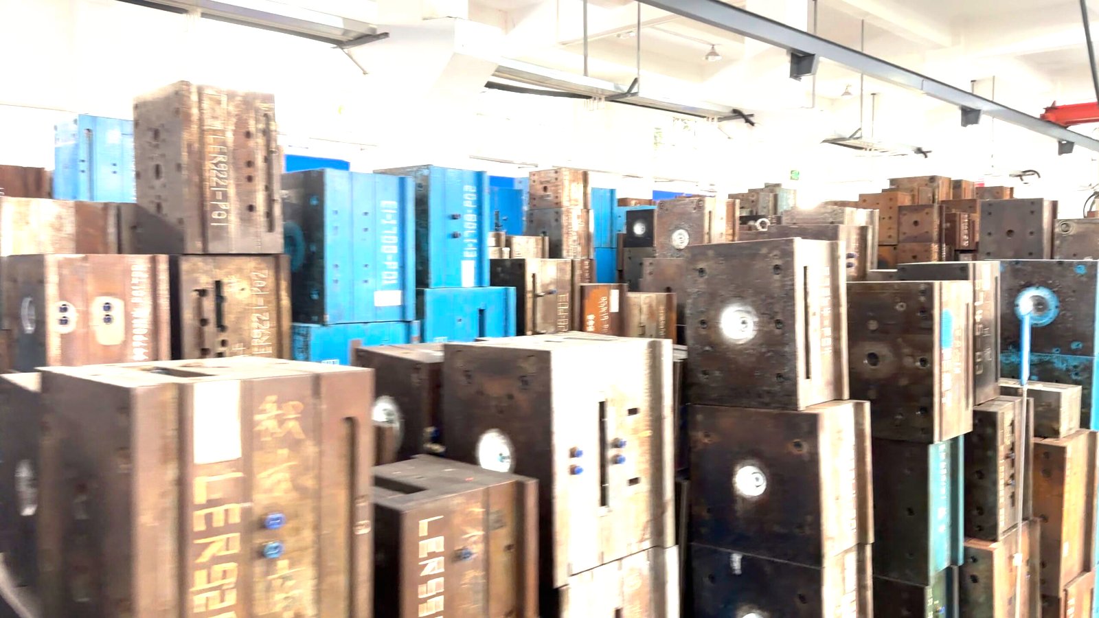
Storage is where more molds are lost than in production. The rules are simple and almost universally broken, because storage is nobody’s job.
| Situation | Correct procedure | What not to do |
|---|---|---|
| Overnight, on the machine | Blow the water out of every circuit, close the mold without clamping hard, cover it | Leave water in the channels "until tomorrow", or clamp to full tonnage overnight |
| Off the machine, up to three months | Clean, dry completely, neutral rust preventive on cavities and shut-offs, grease pins and ways, close, desiccant bag, on a timber pallet | General-purpose grease with EP additives as a rust preventive, or a PVC sheet as a cover |
| Long term, over three months | VCI film wrap plus desiccant, humidity indicator card, timber case, inspect and re-grease every six months | Seal it and forget it. Six months of condensation inside a sealed case ruins a polished cavity |
| Vertical against a wall | Never for anything but the smallest tools. Store flat on bearers | Standing a large mold on end. The mold base sags under its own weight and the halves no longer align |
| Stacked on another mold | Only with a properly spread load and nothing touching the parting faces | Resting one mold base directly on another mold’s shut-off face |
| On a concrete floor | On timber bearers, at least 100 mm clear | Direct contact, which wicks moisture into the base and rusts the bottom plate first |
Open or closed?
The choice between storing a mold open and closed confuses people, and the answer is that both are used for different reasons. Closed is the default: it protects the cavity from dust and from knocks, and it keeps the two halves as a matched pair. But closed means the shut-off faces are in contact, so it should be closed gently and left unclamped — clamping a stored tool puts the leader pins under load for months and presses the shut-offs together with nothing to gain.
Open is for tools with deep cores or fragile inserts, where closing would risk contact damage, or where the cavity needs to be visible for periodic inspection. Then the halves are separated by timber spacers on the mold base, never on the cavity.
The one rule with no exceptions is that a large mold is stored flat. A mold base standing on end deflects under its own weight; after a year the plates are no longer parallel, and the first symptom is uneven flash that no amount of re-spotting will fix, because the base itself is bent. Small tools up to perhaps 300 mm can stand, in a rack, on their base plates.
Label the storage position with four facts: mold number, cavity count, date of last run, date of next inspection. Without those, a tool sits for three years and is discovered missing its ejector pins when someone finally needs it.
Shipping a mold across an ocean
If you are buying a tool from overseas, this is the section that decides whether you receive a mold or a restoration project. A sea container is a hostile environment: humidity above 80 % for weeks, temperature swings of 20 °C between day and night, and salt in the air on deck routes. The temperature swing is the dangerous part, because it produces condensation on any cold steel surface — the phenomenon the freight industry calls container rain.
A proper export preparation has six steps, and a supplier who cannot describe all six has not shipped many tools.
- Clean and dry. Every circuit blown out with dry compressed air until no mist comes out, cavities wiped and dried, no residual cutting fluid in blind holes.
- Protect. Neutral rust preventive on all exposed steel, a heavier film on cavities and shut-offs, grease on pins, ways and slides.
- Wrap. VCI film in contact with the tool, sealed. The vapour saturates the enclosed space and protects surfaces the film does not touch.
- Dry the air inside. Desiccant calculated by volume, not by habit — several hundred grams per cubic metre of enclosed space, plus a humidity indicator card that can be read without opening the wrap.
- Fix the tool in the case. Timber bearers under the mold base, timber blocks bracing the plates so the leader pins carry no load in transit, and a closed mold held by shipping blocks. A tool that shifts in a container arrives with a bent guide system.
- Document before and after. Photographs at packing, the humidity card reading at dispatch, and a note of what was applied. This is the only evidence that supports a claim, and it costs a supplier ten minutes.
On arrival, do not open the wrap in a cold workshop. Let the case sit at room temperature for a day, then open, read the humidity card, photograph it, and inspect before cleaning anything off. The protective film is meant to be removed just before the tool goes on the machine — and if the tool will sit for months before first use, re-protect it rather than leaving it bare.
This is also the point where the handover package matters. A tool with no water diagram and no hot runner wiring schedule cannot be maintained by anyone but the shop that built it. What should be in that package is set out in what to collect at mold trial, and it belongs in the purchase order, not in a conversation.
The mold log that pays for itself
Every tool should have a record, and it should live with the tool rather than in someone’s email. A single sheet, updated by hand, covering six fields per event: date, shot count, resin, what was done, who did it, and what was replaced.
Three uses justify the effort. The first is diagnosis: if the same slide has been re-shimmed three times, the problem is the slide design, not the operator, and no amount of further shimming will fix it. Without a log, that pattern is invisible and the fourth repair looks like bad luck.
The second is polish history. Every polish removes a few microns of steel, and every removal changes the cavity dimension and flattens the texture. A tool that has been polished eleven times has a different cavity depth from the one it was built to, and the parts will show it — usually as flash at the parting line, because the shut-off has been stoned back repeatedly. Recording each polish turns an unexplained drift into a known quantity.
The third is value. A used mold with a complete log is worth materially more than an identical one without, because the buyer can see what has been done. That matters if the product line is ever sold, moved to another molder, or written off.
There is also a human effect worth mentioning: a log with a signature column gets filled in. A form without one does not.
Spares to order with the tool
Spare parts are cheapest on the day the tool is built, when the drawings are open and the supplier still has the material on the shelf. Ordered later, the same pin arrives by airfreight after a two-week wait, during which the tool is idle.
| Spare | Quantity | Why it has to ship with the tool, not later |
|---|---|---|
| Ejector pins, the two or three sizes used | 4 each | Pins bend on a sticky part. A bent pin damages its bore, so the fix has to be immediate. Waiting for an airfreight delivery means the tool sits idle |
| Springs for ejector and slide return | 2 sets | Springs fatigue and take a set. A weak return spring causes plate slam, which cracks cores |
| O-rings and water fittings | 1 full set plus 4 | Rubber perishes in storage. The fittings are often an odd thread that the local supplier does not stock |
| Hot runner heaters and thermocouples | 1 per zone | A single failed heater stops the tool, and the replacement must match the original wattage and length exactly. Five years from now that part number may be gone |
| Limit or proximity switches | 2 | The cheapest part in the tool is the one that stops it most often when it fails |
| Slender core inserts | 1 set | Thin cores break. If the insert is not a standard size, a replacement has to be machined from the original drawing |
| Documentation set | 2 copies | Water circuit diagram, hot runner wiring diagram, steel certificates, spare part list, and the drawing the tool was built to. Without these, any repair is guesswork |
The hot runner items are the ones people regret. A heater is a consumable with a finite life, and it fails without warning. A replacement must match the original in wattage, length, diameter and thermocouple type. When a tool is five years old and the controller is a discontinued model, sourcing that heater becomes a project. Ordering one per zone with the tool costs a fraction of a new manifold plate and eliminates the scenario entirely.
Alongside the parts, ask for the drawings: the cavity insert drawing, the water circuit layout, the hot runner wiring diagram, and the steel certificates. These are produced during mold design and building and should be handed over as a set, not assembled retroactively. They are not nice to have. A toolroom asked to repair a mold without a water diagram will drill a new circuit rather than clean the old one, because drilling is faster than guessing.
Repair or replace: seven decision points
At some point every tool reaches a decision. The answer is not a matter of opinion; it follows from how much material removal the repair requires and how much the tool has left.
| Condition | Verdict | Reasoning |
|---|---|---|
| Peening under 0.05 mm on the shut-off | Repair | Re-spot the faces and stone them flat. Note that removing material changes the stack height, so cavity depth has to be checked afterwards |
| Peening over 0.1 mm across a large area | Usually replace | Removing that much closes the shut-off everywhere else. After two rounds the cavity depth is out and the part thickness is out with it |
| Chipped cavity edge | Depends on size | A small chip can be laser-welded or inset, but a weld patch will not take the same texture or polish as the parent steel, so it shows on a cosmetic part |
| Worn leader pin bores | Repair | Rebush and ream. This is routine and restores alignment completely, provided the base plate is not cracked |
| Worn slide ways | Repair | Replace the wear plates and re-fit. Much cheaper than a new slide, and it removes the flash at the slide shut-off |
| Blocked water circuit that will not descale | Often terminal | Drilling out a circuit or replacing a water plate approaches the cost of a new mold base. This is the failure that most often ends a tool’s life early, and it is entirely preventable |
| Cavity dimensions drifting after repeated polishing | Depends | Each polish removes a few microns. On an insert, replace the insert. On an integral cavity, the machining cost can approach a new tool |
Two rules behind every repair decision
Two general rules sit behind that table.
Steel can only be removed, never added. That asymmetry governs every repair. Re-spotting a parting face lowers the stack height; polishing a cavity enlarges it; re-cutting a gate changes its diameter. So a tool should be built with the shut-off slightly high and the cavity slightly on the small side of nominal, precisely so that future correction has somewhere to go. A mold built dead on nominal has no repair path, and that is a design decision made at quotation stage, not a maintenance decision made later.
Compare against the replacement cost, not the repair cost. A repair that costs more than roughly half of a new tool, on a mold that has already run past its expected life, is money spent on a tool that will fail again somewhere else next quarter. The counter-case is a tool that is expensive because of its size or its hot runner: there, a substantial repair is still the right answer, because the alternative is not half the price.
There is also a contractual question that decides how a repair gets paid for, and it is settled long before the repair. Is the warranty written in shots or in months? Who decides that a tool has reached the end of its life, and against what criterion? A warranty of "one year" on a tool that runs 2 million shots a year and a warranty of "500,000 shots" on one that runs slowly are very different promises. Those clauses belong in the purchase order next to the other terms covered in how to vet an injection molding supplier, not added after the first failure.
For a tool that is being replaced, it is worth understanding where the money went in the first place — the breakdown in what drives the price of an injection mold explains why a large mold base and a hot runner dominate the replacement cost, while the cavity steel is a smaller share than most buyers assume.
What maintenance actually buys
It is difficult to put a number on prevention, so here it is in ratios rather than currency. A tool on a documented maintenance schedule typically reaches one and a half to two and a half times the shot count of an identical tool that receives none — not because maintenance makes steel stronger, but because the failures that end a tool’s life early are almost all preventable ones. A major refurbishment, when it comes, runs at roughly a third to a half of the price of a new tool, and it restores the tool to something close to its original condition rather than improving it.
The larger effect is not on tool life at all. It is on the piece price. A mold with a peened shut-off produces flash that someone has to trim. A mold with a blocked vent produces burns that cannot be sold. A mold with a scaled circuit forces a longer cycle, and cycle time is the single biggest driver of piece cost. None of these appear in the original quotation, and all of them are set by how the tool is treated after it arrives.
Which is the argument for spending a little on the boring end of the project. The steel selection, the runner configuration and the build quality decide what the tool is capable of. Maintenance decides whether you ever get that capability. A tool that arrives with a water diagram, a spare parts kit and a maintenance card is a tool that will still be running when the product it makes has been through three design revisions.
Building a tool that has to last a decade?
Every mold we build ships with a water circuit diagram, a hot runner wiring schedule, a spare parts set and an initial maintenance record — so the shop that runs it can keep it running, wherever it is in the world.
Frequently asked questions
How often should an injection mold be serviced?
By shot count rather than by calendar, with one exception. The working rhythm is a five-minute visual check every shift, a thirty-minute clean and lubricate every week, an inspection with measurements every 50,000 to 100,000 shots, and a full strip-down at roughly 500,000 shots or annually. The exception is a low-volume tool, which may never reach those shot counts; for those, use time instead, inspecting and re-greasing every six months, because rust and seal degradation are the risks rather than wear.
Should a mold be stored open or closed?
Closed, as the default: it protects the cavity, keeps the halves as a matched pair and saves space. The important detail is that it should be closed gently and not clamped, because clamping a stored tool loads the leader pins for months with nothing to gain. Store open only when the tool has deep cores or fragile inserts where closing risks contact damage, and then separate the halves with timber on the mold base, never on the cavity. In both cases the tool lies flat on bearers, never standing on end if it is large.
Can a rusty mold be recovered?
Surface rust usually can, by polishing. The cost is not the labour, it is the material: each polish removes a few microns, flattens the texture and enlarges the cavity, and a texture that has been polished away cannot be put back without re-etching the whole face. Pitting is different. If the pits are deeper than the polishing allowance, the choice is to accept a cosmetic defect in that area or to replace the insert. This is why the effort belongs in prevention — a rust preventive and a desiccant bag cost a fraction of one polishing session.
Why does flash suddenly appear after months of good parts?
Three causes, in order of likelihood. First, peening of the shut-off faces: the steel has been pressed over and no longer meets flat, so more clamp force makes it worse rather than better. Second, worn leader pins or bushings letting the halves close slightly offset, which shows as flash on one side or one corner. Third, a genuine machine issue such as a worn tie bar bushing or a platen deflecting. Check the first two with a feeler gauge along the parting line before touching the machine, because they are far more common and far cheaper to fix.
Does an aluminum mold need different maintenance?
Yes, in three ways. It must be kept dry and coated, because aluminum pits rather than forming a protective oxide layer, and any steel insert in contact with it plus water creates a galvanic couple that corrodes the aluminum at the interface. It should not be cleaned with strong alkaline detergents or blasted with high-pressure water, both of which damage the surface. And its maintenance goal is different: an aluminum tool has a known finite life, so the purpose of maintenance is not to extend it indefinitely but to keep every part in the batch identical, which means watching cavity wear rather than chasing long-term life.
Who should keep the mold log?
The molder who runs the tool, because they are the ones generating the shot counts and the failures. But the log has to start with the tool: the builder should hand over an initial record covering the steel grades used, cavity count, water circuit diagram, hot runner wiring schedule and the drawings the tool was built to. Without that baseline, later entries describe symptoms with no reference point, and any repair becomes guesswork.