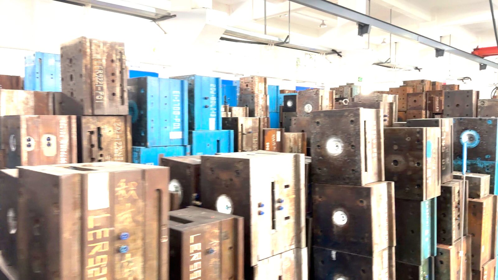


Tonnage is the one number in a mold specification that gets decided in a hurry. It is usually calculated from a rule of thumb, in the last five minutes of a quotation, and it stays wrong for the life of the tool. Too little and the mold flashes, the dimensions drift between shots, and eventually the parting line is peened over. Too much and the tool is squeezed shut so hard that the vents stop working and the steel wears out years early. Both failures are cheap to avoid on paper and expensive to fix in steel.
What clamp force is actually fighting
Injection molding works by pushing liquid plastic into a closed steel box at pressure. That pressure acts on every square millimetre of the part, including the face that lies in the parting plane, and it tries to push the two halves of the tool apart. Clamp force is what holds them together.
The force is not small. A part with 300 cm² of projected area, filled at 40 MPa, generates about 120 kN of separating force per cavity — roughly the weight of twelve tonnes — and it does so in a fraction of a second, every cycle, for the life of the tool. If the clamp cannot hold that, the mold opens by a few hundredths of a millimetre and plastic escapes into the gap. That is what flash is: not a process imperfection, but a structural failure of the clamping balance.
Two clarifications make the rest of this page easier to follow.
- Only the projected area counts. A wall that runs vertically in the tool produces almost no separating force, because the pressure on it pushes sideways against steel. What matters is the outline you would see looking straight down the clamp axis.
- The number is per shot, not per cycle. Clamp force has to be held for the whole of packing, which is when the pressure inside the cavity is at its highest. The peak is not at the end of fill but during the pack, which is why a tool that looks fine on a short shot can still flash in production.
The calculation, in the order it has to be done
The formula is a multiplication. What makes it go wrong is the order and the units, so both are worth writing down.
F (kN) = P (MPa) × A (cm²) × 0.1 × safety factor
P is the cavity pressure from the resin table below, A is the total projected area including every cavity and the runner, and the 0.1 is not magic: 1 MPa is 1 N/mm², a square centimetre is 100 mm², so 1 MPa acting on 1 cm² gives 100 N, which is 0.1 kN. Divide the result by 9.81 to get metric tonnes.
| Step | Value | Where it comes from |
|---|---|---|
| Projected area of one part: 200 × 150 mm | 300 cm² | Bounding outline of the part as seen from the fixed platen, including any face that would flash |
| Cavities | 2 | From the production volume, not from the tonnage |
| Runner and overflow projection, +10% | 660 cm² | Only the parts of the runner that sit in the parting plane |
| Cavity pressure for ABS | 40 MPa | From the resin table below — not from the machine’s injection pressure |
| Required clamp force = 40 × 660 × 0.1 | 2 640 kN | The 0.1 converts MPa × cm² into kN |
| Safety factor 1.15 | 3 036 kN | Covers pressure spikes on transfer and a tool that is not perfectly flat |
| Convert to tonnage at 9.81 kN per metric tonne | ≈ 310 t | Divide by 9.81 |
| Machine selected | 350 t | The next standard size above the requirement |
The example is deliberately ordinary — a 200 by 150 mm two-cavity ABS part, which is the size of thing that gets quoted every day. Read down the middle column and notice how much of the final number comes from decisions that were made before anyone thought about a machine: the cavity count, the pressure the resin needs, and whether the runner sits in the parting plane.
Two habits make this reliable. First, write the unit next to every number at every step, because a bar/MPa mix-up is the single most common way to be wrong by a factor of ten. Second, calculate the tonnage after the cavity count is settled, not before — the volume study decides the cavities, and the cavities decide the tonnage. Doing it the other way round produces a tool that fits an available machine rather than the production plan.
Cavity pressure is not injection pressure
This is where most estimates go wrong, and the error is always in the same direction. A machine rated at 200 MPa of injection pressure does not put 200 MPa into the cavity. That pressure is measured at the nozzle, and by the time the melt has passed the sprue, the runner, the gate and the length of the part, most of it is gone. Cavity pressure at the end of fill is typically a third to a half of nozzle pressure, and it is the cavity figure that pushes the mold apart.
Using the nameplate number therefore overestimates the tonnage by two to three times, which is how a job that needs a 250-tonne machine ends up booked on an 800.
| Resin | Cavity pressure, MPa | Typical value to design to | What pushes it up |
|---|---|---|---|
| PP | 20–40 | 30 MPa | Long flow paths, thin walls, low melt temperature |
| HDPE | 20–40 | 30 MPa | Thick sections need packing pressure rather than high fill pressure |
| GPPS / HIPS | 20–45 | 30 MPa | Thin walls and long flow; the resin itself is easy |
| ABS | 30–50 | 40 MPa | Anything under 1.5 mm wall, or flow over 150 mm |
| PC/ABS | 40–60 | 50 MPa | A cooler tool and thick sections; the blend is stiffer than ABS |
| PMMA | 40–60 | 50 MPa | Optical parts are usually thick, so packing dominates |
| PC | 50–80 | 65 MPa | High viscosity; a cold tool makes it much worse |
| PA6 / PA66 | 40–70 | 55 MPa | Crystallisation and fast filling |
| POM | 40–70 | 55 MPa | Tight tolerances and small gates |
| PBT | 40–70 | 55 MPa | Fast fill rates that keep the melt from freezing |
| PPS | 50–80 | 65 MPa | Very high viscosity, hot tool, expensive to get wrong |
| Any grade + 30% glass fibre | Add 20–30% | — | Fibres raise viscosity sharply and block thin gates |
| Thin wall, flow ratio over 200 | 80–120 | — | Packaging and electronic housings; the tonnage follows the fill, not the material |
The important thing about that table is that it is a starting point, not a measurement. Cavity pressure rises with flow length, falls with wall thickness and melt temperature, and rises sharply with the addition of glass fibre. A part that needs 40 MPa at 2 mm wall can need 90 at 1 mm, which is a different machine. Where the flow ratio is high, the fill requirement decides the tonnage and the resin table only sets the floor.
For a tool where the number really matters — a large part, an expensive tool, or a high-volume job where the machine is booked for years — the honest route is a mold flow analysis, or a pressure sensor in the cavity on the first trial. Both replace an estimate with a measurement, and the measurement is usually within 20% of a well-judged table value.
Projected area, and the three things people forget
Projected area is the outline of everything that sits in the parting plane and is exposed to melt pressure. Three components get left out of estimates often enough to be worth naming separately.
Every cavity
The area is per cavity, and multi-cavity tools are where the biggest errors happen. An eight-cavity family tool with 80 cm² per part has 640 cm² of projected area before the runner, and that is a machine of a completely different size from the single-cavity version of the same part. It is also why the cavity count belongs to the volume decision, and the machine belongs to the cavity count.
The runner, but only where it lies flat
A cold runner sits in the parting plane and pushes the tool apart exactly like a part does. For a small part with a generous runner system it can be 20–30% of the total; for a large part it is negligible. A hot runner contributes almost nothing, because the melt is still inside the manifold when the pressure peaks — one of the few places where a hot runner reduces the machine requirement rather than increasing it. The trade-offs between the two are covered in hot runner versus cold runner.
Sliders, and why they do not count
This one is counter-intuitive and it comes up in every tool with a side action. A slider’s face is exposed to melt pressure, and that pressure is real — but it acts sideways, perpendicular to the clamp axis. It does not try to open the mold; it tries to push the slider back. What resists it is the locking block or the wedge, not the clamp, and if that block is undersized the slider moves and the part grows a step at the split line. So a slider needs its own force calculation, in its own direction, and adding its area to the clamp force is a mistake that over-sizes the machine.
There is one exception. If a slider face is angled or faces partly along the clamp axis, part of the force does act in that direction, and that component does belong in the total. It is rare, and it is worth a second look on any tool where a slider runs at an angle to the parting plane.
Tonnage is one of eight constraints
A machine that has enough clamp force but cannot fit the mold is not a machine for this job. Sizing is a checklist, not a single number, and the other seven items are the ones that turn up late.
| Constraint | Requirement | What happens when it is not met |
|---|---|---|
| Clamp force | At least the calculated value × 1.1 to 1.2 | Flash at the parting line, dimensions that drift between shots, and a mold that gets damaged once the flash is trimmed |
| Distance between tie bars | Mold width and height both smaller than the clear distance | The tool physically does not fit, and no amount of tonnage helps |
| Mold height range | Between the machine’s minimum and maximum daylight | Too thin and the clamp cannot build force; too thick and it will not close at all |
| Opening stroke | At least twice the part height, plus room to reach in | The part cannot be removed, or it is dragged out and damaged |
| Ejection stroke and force | Stroke at least the part height; force matched to the part stiffness | Parts stick, ejector pins punch through, or the part is pushed out of shape |
| Shot capacity | Part plus runner weight × cavities, at no more than about 80% of barrel capacity | Incomplete plasticising, inconsistent melt, and degradation from excessive residence time |
| Injection rate | Enough to fill the cavity before the flow front freezes | Short shots at the far end, and a weld line that cannot be moved |
| Platen size and rigidity | Platen at least as large as the mold base, and stiff enough to spread the force | The plate bows, the mold flashes in the middle, and the tool wears unevenly |
The tie bar distance is the one that ends discussions fastest. A mold that is 20 mm too wide for the clear space between the bars does not go in, whatever the tonnage, and the fix is a different machine or a different mold design. It is worth checking before the mold base is ordered rather than after, because at that point the only options are a larger machine or a re-cut base.
The shot capacity rule deserves its own note. The usual guidance is that the combined shot weight should sit between 20% and 80% of the barrel capacity. Below 20% the melt spends too long in the barrel and degrades; above 80% there is not enough cushion for consistent packing. A small part in a huge machine is therefore not a safe choice — it is a quality problem waiting to happen, and the tonnage argument that led there was probably based on the injection pressure mistake described above.
What too much tonnage actually does
Everyone knows that too little tonnage causes flash. Fewer people know that too much causes a different set of problems, and they are harder to diagnose because they do not look like clamping problems at all.
The vents stop venting
A vent is a gap a few hundredths of a millimetre deep at the parting line, sized to let air out and keep plastic in. Clamp the tool harder than it needs and the steel around the vent deflects, the gap closes, and the air has nowhere to go. The result is burn marks at the end of the flow path, short shots in the last corner to fill, and a weld line that is weaker than it should be — all symptoms that normally send people looking at the injection profile, the melt temperature and the gate, when the answer is that the press is squeezing the tool shut.
The tool wears faster and flattens
Parting surfaces are not perfectly flat, and they do not stay flat. Every cycle presses the two faces together with the full clamp force, and any high spot takes the load first. Over a few hundred thousand cycles, a tool run at twice its required tonnage will show peened parting lines, collapsed vents and a shut-off that no longer seals — damage that costs far more than the machine time saved.
The machine is occupied
A press is a fixed asset with a schedule. Booking a 500-tonne machine for a job that needs 180 removes capacity from every other job that genuinely needs 500, and it is invisible in the cost sheet because the rate for a large machine is usually averaged. This is why tonnage over-estimates tend to be discovered late, if at all: the part is fine, the mold is fine, and the only cost is a production plan that is quietly 30% less flexible than it should be.
Tonnes, short tons, and a ten percent trap
The word "ton" does not mean one thing, and in press sizing the difference is large enough to matter.
- A metric tonne is 1 000 kg, which is 9.81 kN. Machines built in Europe and Asia are almost always rated this way.
- A US short ton is 907 kg, which is 8.9 kN. Some North American machines are rated this way.
- A UK long ton is 1 016 kg, 9.96 kN. Rare now, but it exists in older documentation.
A tonne is about 10% more force than a short ton, which means a machine rated at 350 in one system is a 385 in the other. If the calculation is done in metric tonnes and the machine is rated in short tons, the real clamp force is 10% lower than assumed — and 10% is roughly the size of the safety factor, so the margin disappears without anyone noticing.
The practical fix is simple: keep the calculation in kilonewtons, and convert at the end using the rating basis written on the machine’s plate. Kilonewtons do not have a nationality.
Thin walls and long flow: when fill decides the tonnage
On a normal part, the tonnage calculation is driven by the resin. On a thin-wall part it is driven by the fill, and the fill is limited by how fast the machine can inject rather than how hard it can clamp.
| Flow length ÷ wall thickness | Injection pressure needed | What it means in practice |
|---|---|---|
| Under 50 | 60–80 MPa | Comfortable; most thick, compact parts sit here and almost any machine will fill them |
| 50–100 | 80–110 MPa | The normal range for housings and enclosures; gate position starts to matter |
| 100–150 | 110–140 MPa | Long or thin parts; a hot runner and a warm tool are usually needed to stay in range |
| 150–200 | 140–180 MPa | Demanding; the tool needs generous gates and the machine needs high injection rate |
| Over 200 | 180 MPa and up | Thin-wall packaging territory: high-speed injection, often a dedicated accumulator, and tonnage driven by fill pressure |
The flow ratio is the length the melt has to travel from the gate to the last point to fill, divided by the wall thickness. It is the single best predictor of whether a part will be easy or hard to mold, and it explains most of the surprises in tonnage estimation: two parts of the same projected area and the same resin can need completely different machines if one has a flow ratio of 60 and the other of 220.
For thin-wall work the pressure needed to fill is high, and it acts on the full projected area, so the tonnage rises with it. This is the one case where the injection-pressure mistake is less damaging, because the numbers genuinely are large. It is also the case where injection rate matters most: a machine that can reach the pressure but not the speed will short-shot at the far end while the pressure gauge reads comfortable. Wall thickness and its effect on the whole cycle is covered in the DFM checklist.
Not sure what machine your mold needs?
Send us the part drawing and the annual volume. We will come back with the cavity count, the projected area, the tonnage with a stated safety factor, and the machine constraints — before anyone orders a mold base that turns out not to fit.
How to prove the number was right
A calculated tonnage is an estimate, and estimates deserve a test. Three checks, in increasing order of cost, settle the question.
The flash test
Run the tool at the calculated tonnage with the process at normal production settings and inspect the parting line. Then reduce the clamp force in steps until flash appears. The difference between the production setting and the flash point is the real margin. If flash appears at 95% of the calculated figure, the estimate was optimistic; if it appears at 60%, the tool is over-clamped and the vents are probably being squeezed. This test takes twenty minutes and needs nothing but the machine.
The short shot
Turn the shot size down until the cavity is roughly 95% full, then bring it up in small steps while watching where the flow front stops. The pressure at which the part completes is close to the pressure the tool sees in production, and it is a direct check on whether the resin table value was reasonable. A part that fills at half the assumed pressure is a part whose tonnage was overestimated, usually by a wide margin.
Cavity pressure sensing
A pressure sensor behind an ejector pin or flush with the cavity wall measures the real curve, shot after shot. It is the only method that shows the peak during packing rather than the average during fill, and on a large or expensive tool it pays for itself the first time it prevents a machine from being selected wrongly. The same instrumentation is what makes a trial decision defensible, which is the subject of mold trial approval.
Eight mistakes that show up in real quotations
Almost every tonnage error belongs to a small set, and the useful thing about the set is that each one has a symptom you can recognize without redoing the arithmetic. That matters, because the person checking the number is rarely the person who calculated it.
| Mistake | Symptom | Correction |
|---|---|---|
| Using the machine’s injection pressure as the cavity pressure | Tonnage overestimated by two to three times; a machine is booked that is far larger than needed | Cavity pressure is a fraction of injection pressure after the losses in the nozzle, sprue and runner. Use the resin table, not the nameplate |
| Forgetting the number of cavities | Severe under-tonnage and flash from the first shot | Projected area is per cavity; multiply before applying the safety factor |
| Forgetting the runner in the parting plane | Flash along the runner, which is often mistaken for a clamp problem | Add 10–20% for a cold runner; a hot runner needs almost nothing |
| Mixing bar and MPa | A result that is wrong by a factor of ten, in either direction | Convert everything to MPa before the calculation, and write the unit next to every number |
| Adding slider projection to the clamp force | Over-tonnage; a machine is chosen that is bigger than the job needs | A slider’s face is pushed sideways, not along the clamp axis. It needs a locking block, not clamp force |
| Ignoring the overflow or flash land | Flash appears in a place that was never designed to seal | Only the surface that actually seals counts, and it has to be designed in |
| No safety factor at all | The tool works on the first trial and flashes after two hours of running | 1.1 to 1.2, because cavity pressure spikes at transfer and a warm mold seals differently |
| Rounding down to the nearest machine | An overloaded press and a tool that is damaged before its first approval | Round up to the next standard size; a slightly larger machine costs far less than a damaged mold |
Two rows in that table cause most of the damage. Using the machine’s nameplate pressure over-sizes the press by a factor of two to three, and the error is hard to see because the answer looks plausible — a large part gets a large machine, and nobody questions it. Adding slider area to the clamp force does the same thing on any tool with a side action, and it is the usual reason a tool ends up permanently tied to a press much bigger than it needs.
Ten checks before the machine is booked
- Is the projected area per cavity, and is the number of cavities settled? Volume decides cavities; cavities decide tonnage.
- Is the runner included, and is a hot runner correctly excluded? Cold runner adds 10–20%; a hot runner adds almost nothing.
- Is the cavity pressure taken from the resin, not from the machine’s nameplate? This one mistake accounts for most over-sized bookings.
- Is the flow ratio under control? Above 150, the fill requirement starts to set the tonnage.
- Is the safety factor between 1.1 and 1.2? Lower is not brave; it is a flash problem scheduled for later.
- Are the units consistent all the way through? MPa and cm², or bar and cm² — never a mixture.
- Does the mold fit between the tie bars, and within the mold height range? Check the drawing, not the memory.
- Is the shot weight between 20% and 80% of barrel capacity? Below 20% is a degradation problem, not a safety margin.
- Is the tonnage rating basis known — metric tonne or short ton? A 10% difference, which is the whole safety factor.
- Has anyone planned the flash test? A calculation nobody verifies is a guess with a decimal point.
None of this requires a simulation, and all of it fits on one page of a quotation file. The reason it is worth doing is that tonnage errors are asymmetric: the cost of getting it slightly too high is a larger machine and a worn tool, and the cost of getting it too low is a flashing mold, drifting dimensions, and eventually a damaged parting line. The cheaper error is the one to design towards, which is why the rule is to round up — but only after the number has been calculated properly, not instead of calculating it.
The tonnage also has to be read together with the other physical decisions about the tool: which steel it is made from, in mold steel selection; how the heat leaves it, in mold cooling design; how many cavities it should have, from mold cost and volume; and what it costs when the tolerance is tighter than the process can hold, in injection molding tolerances. Where a smaller machine is genuinely enough — small batches in aluminum tooling, for instance — the arithmetic is set out in low volume injection molding, and the whole sequence from drawing to press is in the plastic injection molding guide.
Frequently asked questions
Is there a quick rule of thumb for tonnage?
For a normal part in a commodity resin, roughly 0.4 to 0.5 tonnes per square centimetre of projected area gets you into the right range, because that is what 40 MPa works out to. The rule is useful for a sanity check and dangerous as a basis for ordering a machine: it is only correct at one pressure, and pressure varies by a factor of three across the resin table. Use it to catch a mistake in the full calculation, not to replace it. For thin-wall parts the rule underestimates badly, and for a large thick part in PP it overestimates.
Why does the same mold behave differently on two machines of the same tonnage?
Because tonnage is only one of the eight constraints, and the others differ more than people expect. Platen size and stiffness change how evenly the force is spread across the mold base; shot capacity changes the melt history; injection rate changes where the flow front freezes; and the tie bar distance decides whether the mold sits centered or offset. Two 250-tonne machines from different builders are not interchangeable for a demanding tool, and it is common for one to run a job comfortably while the other flashes — not because of the tonnage, but because of how the force is applied.
Does a hot runner reduce the tonnage I need?
Slightly, and for a reason that is easy to miss: the melt in a hot runner stays inside the manifold until it reaches the gate, so the runner itself contributes almost no projected area in the parting plane. On a small part with a large cold runner that can be a 10–20% reduction in required clamp force. On a large part it is negligible. The reduction is real but it is not the reason to choose a hot runner — that decision is about scrap, cycle time and gate quality, and it usually adds cost and complexity that the tonnage saving does not pay for.
Can I run a mold on a machine with less tonnage if I lower the pressure?
Sometimes, and it is a real technique rather than a fudge. Lowering the cavity pressure lowers the separating force proportionally, and if the part still fills and packs acceptably, the tool will run. The limits appear quickly: less pressure means less packing, which means more shrinkage and less dimensional control, and it usually shows up first as sink on thick sections and as a heavier weld line. It is a reasonable way to use an available machine for a short run, and a poor way to plan a production tool, because the process window ends up narrow and the part quality moves with every small variation in resin lot.
How much safety factor is right?
Between 1.1 and 1.2 for a normal tool, and there are three things it is covering: the spike in cavity pressure at the transfer from fill to pack, which is typically 10–20% above the fill pressure; the fact that a mold base is not perfectly flat and the force concentrates on high spots; and the difference between the resin’s table pressure and what the actual part geometry demands. Anything above 1.3 is not safety, it is an admission that the cavity pressure was not known — and the consequences of over-clamping, closed vents and worn parting lines, are real.
Who decides the tonnage — the mold maker or the molder?
It has to be agreed between them before the mold base is ordered, because the tonnage determines the mold base size and the mold base size determines which machine it fits. In practice the mold maker calculates it, because the projected area and the cavity count are mold decisions, and the molder confirms it against the machines actually available. The failure mode to avoid is a tool designed to the tonnage limit of one specific press: it works perfectly until that press is booked, and then the tool cannot be moved, which removes the flexibility the purchase was supposed to buy.