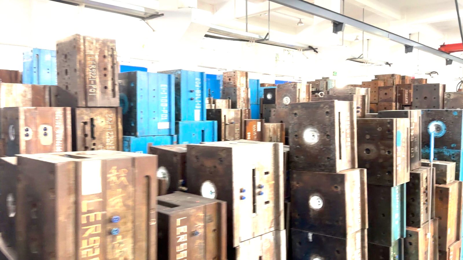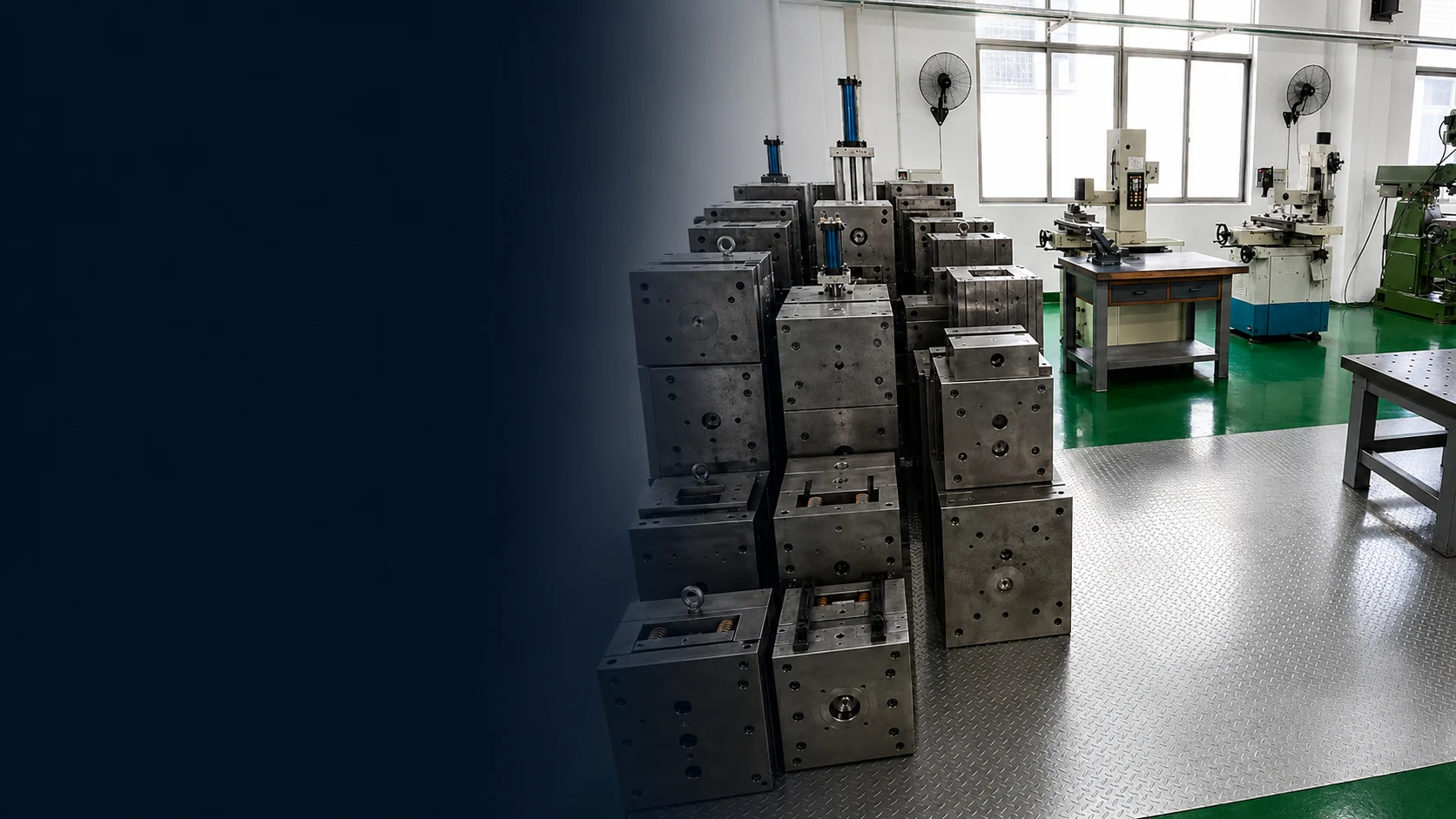


Plastic injection molding turns thermoplastic pellets into finished parts by melting the resin, forcing it into a closed steel mold under pressure, and cooling it until it holds its shape. Nearly every molded component in a home, a car or a medical device comes off this cycle — and the decisions that matter most are made long before the first shot: the part design, the mold structure and the resin choice.
What Plastic Injection Molding Is
Injection molding is a repeatable, high-pressure forming process. Plastic pellets are melted in a heated barrel, injected into a machined steel cavity at pressures typically between 500 and 1,500 bar, held there while the polymer solidifies, and then ejected as a finished — or near-finished — part.
Two things are always present, and everything else follows from them:
- A machine that melts, injects and clamps. It controls temperature, pressure, speed and time.
- A mold that defines the geometry. It is the single largest fixed cost of the project and the single largest influence on part quality.
The process is used almost exclusively with thermoplastics — polymers that soften when heated and harden when cooled, so scrap and runners can be reground and remolded. Thermosets and liquid silicone can also be injection molded, but they cross-link permanently and need different machines, molds and process windows.
The economic rule of thumb: injection molding becomes competitive once annual volume passes roughly 2,000–5,000 pieces per part. Below that, the tooling cost per part is too high and processes without a mold — CNC machining, urethane casting or 3D printing — usually win. Above it, the mold cost is amortized across enough parts that the per-part price drops below almost any alternative.
The Injection Molding Cycle, Step by Step
Every shot runs through the same five stages. Understanding their shares of the cycle explains most cost and quality decisions later on.
| Stage | What happens | Share of cycle |
|---|---|---|
| 1. Clamping | The moving platen closes the mold and full clamp tonnage builds to resist injection pressure | 2–8% |
| 2. Injection / filling | The screw advances and pushes melt through the nozzle, sprue, runner and gate into the cavity | 5–15% |
| 3. Packing / holding | Pressure is held while the gate freezes, compensating for volumetric shrinkage as the part cools | 5–15% |
| 4. Cooling | Heat is removed through the mold steel and waterlines until the part is rigid enough to eject | 50–70% |
| 5. Ejection | The mold opens and pins, sleeves or a stripper plate push the part out; the mold then closes again | 5–10% |
Why cooling dominates
Cooling accounts for roughly half to two thirds of the cycle, and it is governed by wall thickness. Heat has to leave the part through the steel, so cooling time scales with the square of wall thickness: doubling a wall from 2 mm to 4 mm roughly quadruples the cooling time. A part that looks only slightly heavier can therefore cost twice as much per shot.
That single relationship is why wall-thickness uniformity is the most important design rule in injection molding. It is also why a well-designed cooling circuit — waterlines close to the cavity surface, baffles or bubblers in deep cores, and increasingly conformal cooling inserts — pays for itself within production.
Packing is not optional
Plastic shrinks as it cools. If injection stops the moment the cavity is full, the part contracts away from the steel and you get sink marks, voids and dimensions that drift below tolerance. The packing stage keeps pressure on while the gate is still open, feeding extra melt in to compensate. Cut hold time or hold pressure and the defect appears at the thickest section, not the thinnest.
The Injection Molding Machine
A machine has two halves, and both constrain what you can mold.
Clamping unit
The clamping unit opens and closes the mold and holds it shut against injection pressure. Its rating is clamp tonnage. A working estimate for the tonnage a part needs is:
Required clamp force (tonne) ≈ projected area (cm²) × cavity pressure (kgf/cm²) ÷ 1,000
Cavity pressure runs around 300–500 kgf/cm² for commodity resins and ordinary walls, and considerably higher for thin walls, long flow paths and engineering resins. Projected area is the shadow of the part — plus the runner — on the parting plane, multiplied by the number of cavities.
Injection unit
The injection unit is a rotating screw inside a heated barrel. Rotation melts and conveys resin; axial travel injects it. Three numbers matter:
- Shot size — the maximum volume of melt the barrel can deliver in one cycle. The part plus runner should sit between about 20% and 80% of it. Too small and the melt spends too long in the barrel and degrades; too large and residence time is short and the process becomes unstable.
- Screw diameter and L/D ratio — larger diameters give more shot capacity but lower achievable pressure; longer screws give better mixing.
- Injection pressure and rate — the two variables operators adjust most, alongside melt temperature and hold pressure.
Our own production floor runs machines from 50 to 500+ tonnes, which covers everything from small precision connectors to large automotive and houseware parts. Choosing the machine is not about the biggest available unit — it is about matching shot size and tonnage closely to the part so the process window stays wide.
The Mold: What Is Actually Inside It
A mold is two halves that meet at the parting line. The cavity side (fixed half) forms the outside surface; the core side (moving half) forms the inside and carries the ejection system. Between them sit the systems that make the difference between a tool that runs for a million shots and one that fights you every cycle.
Core systems
- Cavity and core inserts — the actual part geometry, usually separate blocks in a standard mold base so they can be replaced or re-cut.
- Runner and gate system — carries melt from the sprue to the cavity. Gate type (edge, side, pin-point, submarine, cashew, hot tip, valve gate) determines where the part can be gated, whether degating is automatic, and where weld lines land.
- Cooling circuit — drilled waterlines, baffles, bubblers or a hot-runner-cooled manifold. Channels are normally placed 1.5–2.5 diameters from the cavity surface and spaced 2.5–5 diameters apart.
- Ejection system — ejector pins, sleeves, stripper plates or lifters. The choice depends on part geometry and where marking is acceptable.
- Venting — shallow grooves at the parting line, typically 0.02–0.03 mm deep for polyolefins and 0.01–0.02 mm for engineering resins. Inadequate venting is the most common cause of burn marks and short shots.
- Sliders and lifters — release undercuts and side holes. Every one adds cost, adds a failure mode, and adds cycle time.
- Hot runner manifold — keeps melt molten to the gate, eliminating runners and regrind. It raises tool cost but lowers material waste and cycle time on multi-cavity work.
- Guide pillars and bushes — keep the halves aligned so wall sections stay concentric shot after shot.
Steel selection
The steel grade sets mold life, polishability and price. Pre-hardened grades such as P20 and 718H (roughly 30–36 HRC) suit most commodity and houseware tools at 100,000–500,000 shots. Through-hardened stainless grades such as S136 or 1.2083 (48–54 HRC) are used where corrosion resistance and optical polish matter — PVC, PC, medical and transparent parts — and reach a million shots and beyond. Hot-work grades such as H13 and 8407 handle glass-filled resins and high melt temperatures.
We keep more than 50 steel grades in the material library for this reason: the right choice is a function of resin, volume, surface requirement and tolerance, and getting it wrong is expensive either way — too soft and the tool wears out mid-program, too hard and you paid for life you will never use.
Choosing the Resin
Resin choice fixes the mechanical behavior, the shrinkage, the drying requirement and much of the process window. The table below covers the grades we mold most often.
| Resin | Why it is chosen | Typical parts | Mold shrinkage |
|---|---|---|---|
| PP | Cheap, tough, living hinge, good chemical resistance | Containers, caps, housewares, automotive trim | 1.0–2.5% |
| HDPE / LDPE | Low cost, waxy surface, food safe | Crates, closures, bins, toys | 1.5–4.0% |
| ABS | Good impact strength, excellent cosmetic finish, easy to plate and paint | Appliance housings, electronics enclosures | 0.4–0.7% |
| PC | High impact, transparent, heat resistant; needs drying | Lenses, machine guards, power tool housings | 0.5–0.7% |
| PC/ABS | Balance of PC toughness and ABS flow and finish | Automotive interior, laptop and device shells | 0.4–0.6% |
| PA6 / PA66 | Wear resistance, strength, glass-filled grades for stiffness; hygroscopic | Gears, brackets, clips, structural components | 0.5–2.0% |
| POM | Low friction, high fatigue and creep resistance, dimensionally stable | Gears, bearings, latches, conveyor parts | 1.8–2.5% |
| PBT / PET | Rigid, heat resistant, good electrical properties | Connectors, switch housings, pump bodies | 0.9–1.8% |
| PMMA | Optical clarity and UV stability, but brittle | Light guides, display covers, lenses | 0.2–0.6% |
| PVC (rigid / flexible) | Flame retardant, chemical resistant; corrosive to steel | Pipe fittings, cable ducts, gaskets | 0.3–0.6% |
| TPE / TPU | Rubber-like feel, soft-touch, overmoldable onto rigid substrates | Grips, seals, wearable bands, soft-touch handles | 0.5–2.0% |
| PPS / PEEK | High temperature, chemical and dimensional stability; premium price | Under-hood parts, medical and aerospace components | 0.2–0.8% |
Three properties that catch people out
- Shrinkage. Semi-crystalline resins (PP, PE, POM, PA) shrink far more than amorphous ones (ABS, PC, PS, PMMA), and shrinkage is not uniform in every direction. The mold cavity is cut oversized by the shrinkage allowance — which is why the same drawing in PP and in ABS needs two different tools.
- Moisture. PA, PC, PET, ABS and PMMA absorb water from the air. Molded wet, they produce silver streaks, splay and a measurable drop in strength. Drying is a process step, not a suggestion: typically 80–100 °C for 4 hours for PA, 120 °C for 4 hours for PC, 120–140 °C for PET.
- Fillers. Glass fibre raises stiffness and cuts shrinkage, but it also abrades the mold, worsens weld-line strength and demands harder steel and larger gates. A 30% glass-filled PA is a different tooling proposition from unfilled PA.
Where a part has to combine properties — a soft grip on a rigid housing, a sealed insert in a structural body — the answer is usually overmolding or 2K molding or insert molding rather than a single resin. Our material selection and engineering support covers the trade-off analysis when the choice is not obvious.
Design Rules That Decide Cost
Most of a part’s cost is locked in at the design stage. These are the rules that carry the most weight.
Wall thickness
- Keep walls uniform. A variation of more than about 25–30% of nominal thickness creates a thick section that cools last, packs unevenly and produces sink marks or voids.
- Typical nominal walls: ABS and PP 1.5–3.0 mm, PC 2.0–3.5 mm, PA 1.0–2.5 mm, POM 1.5–3.0 mm. Thin-wall molding exists but needs high-speed injection, higher tonnage and hardened tooling.
- To stiffen a wall, add ribs rather than thickness. Stiffness rises with the cube of section height, so a rib is far more efficient than a thicker wall — and it cools faster.
Ribs and bosses
- Rib thickness should be 50–60% of the adjoining wall, height up to about 3× wall, spacing at least 2× wall.
- Boss outside diameter around 2× the inside diameter, wall thickness about 60% of nominal, with gussets or a connecting rib to avoid a free-standing thick mass.
Draft angle
Every vertical face needs draft to release cleanly. 0.5° minimum on smooth walls, 1–2° on textured surfaces, and more on deep cores or fine textures. A useful rule: add about 1° of draft for every 0.025 mm of texture depth. Under-drafted walls produce drag marks, scuffing and ejection strain — and the fix is a mold re-cut, not a process change.
Corners and radii
Sharp internal corners concentrate stress and restrict flow. Use an internal fillet of at least half the wall thickness, ideally equal to it, and match external radii to wall thickness so the section stays uniform through the corner.
Undercuts and side actions
Any feature that cannot be released in the opening direction needs a slider, lifter or split. Each adds tooling cost, maintenance and cycle time. Where a small undercut can be replaced by a press-fit detail, a snap geometry that flexes, or a post-assembly step, doing so is often cheaper over the program than the side action.
Gate location and cosmetics
- Gate into the thickest section so packing can reach the thin extremities.
- Keep gates off visible surfaces; a gate mark is permanent.
- Place gates so weld lines — the seam where two flow fronts meet — land in low-stress, non-cosmetic areas.
- Avoid gating directly into an open cavity: the melt jets and leaves a snake-like trail.
Get a DFM review before the steel is cut
Send us your 3D model or 2D drawing. Our engineers check wall thickness, draft, parting line, gate position, undercuts and cooling, then return a manufacturability report with a mold structure recommendation and a quotation — typically within 24 hours.
Tolerances and Quality Control
Injection molding is precise, but “precise” needs to be defined per dimension rather than declared for the whole part.
- General tolerances of ±0.05 mm are routine on molded features, in line with the ISO 20457 / DIN 16742 framework for plastic parts.
- Critical dimensions can be held to around ±0.01 mm, but only where the dimension is specified as critical, the process is under statistical control, and the gauge is capable. Demanding it everywhere multiplies tool cost and rejects parts that would function perfectly.
- Do not tolerance across the parting line more tightly than the mold can hold, and do not stack tolerances through several components in a single drawing callout.
Surface finish
Finish is specified by standard: SPI grades A1–A3 for high gloss, B1–B3 for semi-gloss, C1–C3 for matte and D1–D3 for textured, or VDI 3400 numbers for spark-eroded textures. Finish and draft are linked — a deep texture on a vertical wall without extra draft will drag. On transparent and optical parts, finish is dictated by polish grade rather than texture, and steel choice moves to a stainless grade.
Verification
A normal production release includes first article inspection (FAI) against the drawing, dimensional reports from CMM or optical measurement, and capability studies on critical features. Regulated programs add PPAP documentation, and medical work adds IQ/OQ/PQ validation. In-process, the controls that matter are shot weight monitoring, cavity pressure sensing and SPC on the dimensions that carry function.
Injection Molding Compared With Other Processes
Injection molding is rarely beaten on per-part cost at volume, but it is frequently the wrong answer at low volume or for simple hollow shapes.
| Process | Tooling cost | Best volume | Geometry limits | Material waste |
|---|---|---|---|---|
| Injection molding | High (steel tool) | 2,000–1,000,000+ pcs | Near-net shape, tight tolerance, complex detail | Low; runners can be reground |
| Blow molding | Medium | 10,000+ pcs | Hollow, closed bodies only | Low |
| Thermoforming | Low | 500–50,000 pcs | Open shells, shallow draw, no undercuts | Medium; sheet trim scrap |
| CNC machining | None | 1–2,000 pcs | Prismatic, deep pockets, no draft needed | High; up to 70% of the billet |
| 3D printing | None | 1–500 pcs | Almost any geometry, weaker layer adhesion | Very low |
| Die casting | High | 5,000+ pcs | Metal parts, thicker walls, draft required | Low |
In practice the decision is a break-even calculation rather than a preference. Compare the mold cost amortized over expected volume against the per-part price of the alternatives, and include the cost of the design changes each process would force. Below roughly 500 pieces the tooling rarely pays back; between 500 and 5,000 a bridge tool in aluminium or a low-cavity steel tool can be the right compromise. For early-stage validation, rapid prototyping and 3D printing is the correct first step, not a shortcut tool.
Common Defects and Their Causes
Almost every molding defect traces back to one of four things: filling, packing, cooling or venting. The table maps the visible symptom to the usual cause and the first correction to try.
| Defect | What you see | Usual cause | First correction |
|---|---|---|---|
| Short shot | Part incomplete, edges missing | Insufficient pressure, cold melt, blocked vent, thin wall | Raise injection pressure and speed, check venting |
| Flash | Thin fin at the parting line or ejector pins | Too much injection pressure, insufficient clamp tonnage, worn mold faces | Reduce pressure, raise tonnage, re-fit mold faces |
| Sink marks | Dimples on the thickest section | Thick wall, insufficient packing, early gate freeze | Core out the wall, extend hold time, raise hold pressure |
| Voids | Internal bubbles in thick sections | Shrinkage pulling material inward, moisture | Increase packing, dry resin, thin the section |
| Weld lines | Visible seam where two flow fronts meet | Gate position, insert or pin blocking flow | Move the gate, raise melt temperature and speed |
| Jetting | Snake-like trail from the gate | Gate too small, fill too fast, poor gate location | Enlarge the gate, aim flow against a wall |
| Silver streaks | Silvery lines near the gate | Moisture in the resin, air entrapment | Dry the resin, improve venting |
| Burn marks | Black or brown scorching at flow end | Trapped air compressed in the cavity, overheat | Open vents, reduce injection speed |
| Warpage | Part twists or bows after ejection | Uneven cooling, unbalanced flow, wrong packing | Balance cooling, equalize wall thickness |
| Drag marks | Scratches on side walls | Insufficient draft, rough core surface | Add draft, polish the steel |
| Flow marks | Wavy pattern opposite the gate | Melt too cold, fill too slow | Raise temperature, increase injection speed |
| Ejector marks | White stress marks or dents at pins | Too few or too small ejectors, part too hot | Add ejector area, lengthen cooling |
Two practical notes. First, defects interact: raising injection speed to fix a short shot can create burn marks if venting is poor, so change one variable at a time. Second, a defect that appears only after a tool has run for months is usually wear or cooling-channel fouling, not a process drift — check the tool before touching the parameters.
What Drives Cost and Lead Time
Tool cost
Four factors dominate: the number of cavities, the mold size and steel grade, the complexity (sliders, lifters, hot runner, unscrewing), and the surface finish and tolerance requirement. Cavitation is the biggest single lever — doubling cavities roughly doubles the mold cost but halves machine time per part, which is why high-volume programs pay for high cavitation and low-volume programs do not.
Part cost
Per-part price breaks down into material, machine time, labour and overhead. Machine time is cycle time divided by cavitation, so the two ways to reduce it are a faster cycle and more cavities. Material is shot weight plus scrap, less whatever regrind value can be recovered. Neither is negotiable in isolation — a lighter part with a longer cycle can cost more than a heavier part that runs fast.
Lead time
A typical schedule for a moderate-complexity tool is design and DFM review, steel and component procurement, machining and EDM, fitting and spotting, then T1 sample shots. First samples usually land in the range of several weeks depending on size and complexity, followed by correction rounds, then pilot and production. Production runs of tens of thousands of parts are usually days, not weeks — the constraint is transportation, not the machine.
The details of how a tool is designed, built and validated are covered in injection mold design and mold building. If the part itself still needs definition, product design, reverse engineering and DFM is where the process should start.
When Plastic Injection Molding Is the Right Choice
Choose it when:
- Annual volume justifies tooling — broadly 2,000 pieces and up, and clearly beyond 10,000.
- The part must be identical shot after shot, with tight tolerances and a consistent cosmetic surface.
- The geometry is complex enough that machining it would be slow, wasteful or impossible.
- You need a wide material choice, including filled, flame-retardant, food-contact and medical grades.
- Assembly can be designed out — snap fits, living hinges, integral bosses and overmolded seals all come free at the molding stage.
Look elsewhere when:
- Volume is under roughly 500 pieces — the tool will never amortize.
- The part is a large, simple, hollow shell — thermoforming or blow molding will be cheaper.
- The part is enormous and single — rotational molding or thermoforming wins on tooling.
- The design is still changing weekly — prototype first, tool second.
For the range of tooling and processes this covers in practice, see our custom plastic injection molding services, and for how mold structures differ once the process is settled, the eight classifications of injection molds.
Frequently Asked Questions
How much does a plastic injection mold cost?
There is no single figure, because the cost is driven by cavity count, mold size, steel grade, complexity and finish. A small single-cavity tool for a simple part sits at one end of the range; a large multi-cavity tool with sliders, a hot runner and a textured finish sits at the other, often an order of magnitude higher. The reliable way to price a project is to send a 3D model and a volume forecast, so the quote can be built on a defined cavity count and steel grade.
What is the minimum order quantity for injection molding?
There is no hard minimum, but an economic one. Below roughly 500–2,000 pieces the mold cost dominates the per-part price and other processes are usually cheaper. Between 500 and 5,000 pieces, a bridge tool or a low-cavity tool can make sense. Above about 5,000 pieces per year, a steel production tool is normally the lowest total cost.
How long does it take to make a mold and get first samples?
It depends on size, complexity and cavity count. A simple tool can reach first samples in a few weeks; a large tool with sliders, a hot runner and complex cooling takes considerably longer. The sequence is design and DFM review, steel and component procurement, machining, EDM, fitting and spotting, then T1 shots. Sampling should be planned as a stage with its own review, not as the end of the build.
What wall thickness should a molded part have?
Most commodity and engineering thermoplastics work well between 1.0 mm and 3.5 mm, with ABS and PP typically 1.5–3.0 mm, PC 2.0–3.5 mm and PA 1.0–2.5 mm. What matters more than the absolute number is uniformity: keep variation within about 25–30% of nominal, and add ribs rather than thickness when the part needs stiffness.
Why do molded parts warp?
Warpage is differential shrinkage. If one side of the part cools faster than the other, or if flow and packing are unbalanced, the part contracts unevenly and bows or twists after ejection. The usual fixes are a balanced cooling circuit, uniform wall thickness, symmetric gating and adequate packing — all of them design and tooling decisions rather than operator adjustments.
Can recycled or reground plastic be used?
Yes, in most applications. Runners and rejects are commonly reground and blended back at 20–30%, with the ratio agreed up front because regrind shortens the polymer chain and reduces impact strength. Regrind is normally excluded where color, optical clarity or a regulated material specification applies, and medical and food-contact work usually requires virgin resin with full traceability.